Nexus: advertise default-route conditional via OSPF with two VNF – set metric (+) – set DR/BDR priority – Verifiche tabelle di routing e database
13.02 2024 | by massimilianoArchitettura di Laboratorio Scenario 1: OSPF with two VNF R1 and R2 represent VNF100 ; R3, R4, R5 and R6 […]
Architettura di Laboratorio Scenario 1: OSPF with two VNF
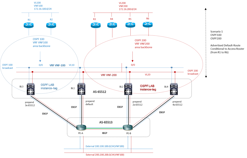
R1 and R2 represent VNF100 ; R3, R4, R5 and R6 represent VNF200 ;
R1 and R2 are the default gateway of subnet IP 172.16.100.0/24: this subnet is advertised via OSPF 100 process in area 0 backbone
R1 and R2 belong at VRF called VNF100 with own ospf process (VRF is configured only on BL devices);
R3, R4, R5 and R6 belong at VRF called VNF200 with different ospf process (VRF is configured only on BL devices)
R3, R4, R5 and R6 are the default gateway of second subnet IP 172.16.200.0/24; this subnet is advertised via OSPF200 process in area 0 backbone
BL1, BL2, BL3 and BL4 are the next stop L3 routing for each Routers (VNFs); BLs are involved on both OSPF process with an instance-tag called LAB and receiving the IP subnets from Routers; furthermore with a mutual redistribution OSPF – BGP, the BLs have the role to advertise the IP Prefix target external domain;
From OSPF domain broadcast we have setting the follow priority for DR and BDR (DR and BDR aren’t preemptive)
BL1 priority 255 (DR role)
BL2 priority 125 (BDR role)
BL3 priority 90 (for redundancy on case of fault DR/BDR)
BL4 priority 50 (for redundancy on case of fault DR/BDR)
all routers 0 (never role DR/BDR)
PE-A and PE-B are the edge routers which are BL1, BL2, BL3, BL4 established session EBGP to advertise IP Prefix from and to external domains
100.100.100.0/24 and 200.200.200.0/24 are the external IP Prefix and belonging at different VRF: target100 to VRF VNF100 and target 200 to VRF VNF200
Template Configuration Nexus Switch Cisco
# feature set
feature ospf
feature interface-vlan
feature lldp
!
# VRF Context
vrf context VNF100
ip route 0.0.0.0/0 null0
!
vrf context VNF200
ip route 0.0.0.0/0 null0
!
# Vlans subnet broadcast BL to Routers
vlan X
name VNF100
vlan Y
name VNF200
!
# Prefix-List to matching external subnets from EBGP and from Routers
ip prefix-list VNF100-IN description from-ext-domain_EBGP-VNF100
ip prefix-list VNF100-IN seq 5 permit < IP_subnet_ext_EBGP_VNF100 >
ip prefix-list VNF100-OUT description to-ext-domain_VNF100
ip prefix-list VNF100-OUT seq 5 permit < IP_subnet_ext_VNF100 >
!
ip prefix-list VNF200-IN description from-ext-domain_EBGP_VNF200
ip prefix-list VNF200-IN seq 5 permit < IP_subnet_ext_EBGP_VNF200 >
ip prefix-list VNF200-OUT description to-ext-domain_VNF200
ip prefix-list VNF200-OUT seq 5 permit < IP_subnet_ext_VNF200 >
!
# route-map to advertising conditional default route ospf to Routers
route-map VNF100-DEF-OSPF_Conditional permit 10
match ip address prefix-list VNF100-IN
set metric < + value > # multiple of ten (10 for BL1, 20 for BL2, 30 for BL3, 40 for BL4)
!
route-map VNF200-DEF-OSPF_Conditional permit 10
match ip address prefix-list VNF200-IN
set metric < + value > # multiple of ten (10 for BL1, 20 for BL2, 30 for BL3, 40 for BL4)
!
# Interface L2
interface Ethernet1/a
description Downstream-Interconnect-SW2
switchport mode trunk
switchport trunk allowed vlan x,y
interface Ethernet1/b
description Downstream-Interconnect-SW1
switchport mode trunk
switchport trunk allowed vlan x,y
# Interface L3
interface Vlan X
description VNF100
no shutdown
vrf member VNF100
ip address < ip_address_subnet_vnf-100 >
ip ospf dead-interval 3
ip ospf hello-interval 1
no ip ospf passive-interface
ip ospf priority < value > # to set DR/BDR (250 for BL1, 200 for BL2, 150 for BL3, 100 for BL4)
ip router ospf < istance-tag > area 0.0.0.0
!
interface Vlan Y
description VNF200
no shutdown
vrf member VNF200
ip address < ip_address_subnet_vnf-200 >
ip ospf dead-interval 3
ip ospf hello-interval 1
no ip ospf passive-interface
ip ospf priority < value > # to set DR/BDR (250 for BL1, 200 for BL2, 150 for BL3, 100 for BL4)
ip router ospf istance-tag area 0.0.0.0
!
# OSPF Configuration
router ospf < instance-tag>
rfc1583compatibility # If Huawei routers running only RFC1583 compatible OSPF.
auto-cost reference-bandwidth 40 Gbps
timers throttle spf 10 100 1000
timers lsa-arrival 50
timers throttle lsa 10 100 1000
passive-interface default
vrf VNF100
router-id < ip_address_router_id >
rfc1583compatibility # If Huawei routers running only RFC1583 compatible OSPF.
auto-cost reference-bandwidth 40 Gbps
default-information originate route-map VNF100-DEF-OSPF_Conditional
timers throttle spf 10 100 1000
timers lsa-arrival 50
timers throttle lsa 10 100 1000
maximum-paths 32
passive-interface default
vrf VNF200
router-id < ip_address_router_id >
rfc1583compatibility # If Huawei routers running only RFC1583 compatible OSPF.
auto-cost reference-bandwidth 40 Gbps
default-information originate route-map VNF200-DEF-OSPF_Conditional
timers throttle spf 10 100 1000
timers lsa-arrival 50
timers throttle lsa 10 100 1000
maximum-paths 32
passive-interface default
Verifiche for OSPF neighbors
R1#sh OSPF neighbor IP
Neighbor ID Pri State Dead Time Address Interface
192.168.1.1 255 FULL/DR 00:00:02 192.168.10.1 Vlan10 → BL1 (DR)
192.168.1.2 125 FULL/BDR 00:00:02 192.168.10.2 Vlan10 → BL2 (BDR)
192.168.1.4 0 2WAY/DROTHER 00:00:02 192.168.10.4 Vlan10 → R2
192.168.1.30 90 2WAY/DROTHER 00:00:02 192.168.10.10 Vlan10 → BL3
192.168.1.40 50 2WAY/DROTHER 00:00:02 192.168.10.20 Vlan10 → BL4
Same behavior output from R2
!
R3#sh OSPF neighbor IP
Neighbor ID Pri State Dead Time Address Interface
192.168.1.6 0 2WAY/DROTHER 00:00:02 192.168.20.6 Vlan20 → R4
192.168.1.7 0 2WAY/DROTHER 00:00:02 192.168.20.7 Vlan20 → R5
192.168.1.8 0 2WAY/DROTHER 00:00:02 192.168.20.8 Vlan20 → R6
192.168.1.11 255 FULL/DR 00:00:02 192.168.20.1 Vlan20 → BL1 (DR)
192.168.1.12 125 FULL/BDR 00:00:02 192.168.20.2 Vlan20 → BL2 (BDR)
192.168.1.31 90 2WAY/DROTHER 00:00:02 192.168.20.10 Vlan20 → BL3
192.168.1.41 50 2WAY/DROTHER 00:00:02 192.168.20.20 Vlan20 → BL4
Same behavior output from APU4, APU5, APU6
From BL1 point of view
BL1# sh ip ospf neighbors vrf VNF100
OSPF Process ID LAB VRF VNF100
Total number of neighbors: 5
Neighbor ID Pri State Up Time Address Interface
192.168.1.2 125 FULL/BDR 01:25:11 192.168.10.2 Vlan10 → BL2 (BDR)
192.168.1.3 0 FULL/DROTHER 01:17:19 192.168.10.3 Vlan10 → R1
192.168.1.4 0 FULL/DROTHER 00:54:53 192.168.10.4 Vlan10 → R2
192.168.1.30 90 FULL/DROTHER 01:25:11 192.168.10.10 Vlan10 → BL3
192.168.1.40 50 FULL/DROTHER 01:25:11 192.168.10.20 Vlan10 → BL4
!
BL1# sh OSPF neighbors IP vrf VNF200
OSPF Process ID LAB VRF VNF200
Total number of neighbors: 7
Neighbor ID Pri State Up Time Address Interface
192.168.1.5 0 FULL/DROTHER 01:04:33 192.168.20.5 Vlan20 → R3
192.168.1.6 0 FULL/DROTHER 01:04:25 192.168.20.6 Vlan20 → R4
192.168.1.7 0 FULL/DROTHER 01:04:11 192.168.20.7 Vlan20 → R5
192.168.1.8 0 FULL/DROTHER 01:04:03 192.168.20.8 Vlan20 → R6
192.168.1.12 125 FULL/BDR 01:34:58 192.168.20.2 Vlan20 → BL2 (BDR)
192.168.1.31 90 FULL/DROTHER 01:34:58 192.168.20.10 Vlan20 → BL3
192.168.1.41 50 FULL/DROTHER 01:34:58 192.168.20.20 Vlan20 → BL4
From BL2 point of view
BL2# sh OSPF neighbors IP vrf VNF100
OSPF Process ID LAB VRF VNF100
Total number of neighbors: 5
Neighbor ID Pri State Up Time Address Interface
192.168.1.1 255 FULL/DR 01:38:40 192.168.10.1 Vlan10 → BL1 (DR)
192.168.1.3 0 FULL/DROTHER 01:30:50 192.168.10.3 Vlan10 → R1
192.168.1.4 0 FULL/DROTHER 01:08:23 192.168.10.4 Vlan10 → R2
192.168.1.30 90 FULL/DROTHER 01:38:41 192.168.10.10 Vlan10 → BL3
192.168.1.40 50 FULL/DROTHER 01:38:41 192.168.10.20 Vlan10 → BL4
!
BL2# sh OSPF neighbors IP vrf VNF200
OSPF Process ID LAB VRF VNF200
Total number of neighbors: 7
Neighbor ID Pri State Up Time Address Interface
192.168.1.5 0 FULL/DROTHER 01:10:27 192.168.20.5 Vlan20 → R3
192.168.1.6 0 FULL/DROTHER 01:10:20 192.168.20.6 Vlan20 → R4
192.168.1.7 0 FULL/DROTHER 01:10:06 192.168.20.7 Vlan20 → R5
192.168.1.8 0 FULL/DROTHER 01:09:57 192.168.20.8 Vlan20 → R6
192.168.1.11 255 FULL/DR 01:40:53 192.168.20.1 Vlan20 → BL1 (DR)
192.168.1.31 90 FULL/DROTHER 01:40:51 192.168.20.10 Vlan20 → BL3
192.168.1.41 50 FULL/DROTHER 01:40:51 192.168.20.20 Vlan20 → BL4
!
From BL3 point of view
BL3# sh OSPF neighbors IP vrf VNF100
OSPF Process ID LAB VRF VNF100
Total number of neighbors: 5
Neighbor ID Pri State Up Time Address Interface
192.168.1.1 255 FULL/DR 01:45:34 192.168.10.1 Vlan10 → BL1 (DR)
192.168.1.2 125 FULL/BDR 01:45:33 192.168.10.2 Vlan10 → BL2 (BDR)
192.168.1.3 0 TWOWAY/DROTHER 01:37:46 192.168.10.3 Vlan10 → R1
192.168.1.4 0 TWOWAY/DROTHER 01:15:21 192.168.10.4 Vlan10 → R2
192.168.1.40 50 TWOWAY/DROTHER 01:45:34 192.168.10.20 Vlan10 → BL4
!
BL3# sh OSPF neighbors IP vrf VNF200
OSPF Process ID LAB VRF VNF200
Total number of neighbors: 7
Neighbor ID Pri State Up Time Address Interface
192.168.1.5 0 TWOWAY/DROTHER 01:24:56 192.168.20.5 Vlan20 → R3
192.168.1.6 0 TWOWAY/DROTHER 01:24:49 192.168.20.6 Vlan20 → R4
192.168.1.7 0 TWOWAY/DROTHER 01:24:35 192.168.20.7 Vlan20 → R5
192.168.1.8 0 TWOWAY/DROTHER 01:24:26 192.168.20.8 Vlan20 → R6
192.168.1.11 255 FULL/DR 01:55:21 192.168.20.1 Vlan20 → BL1 (DR)
192.168.1.12 125 FULL/BDR 01:55:21 192.168.20.2 Vlan20 → BL2 (BDR)
192.168.1.41 50 TWOWAY/DROTHER 01:55:21 192.168.20.20 Vlan20 → BL4
Same behavior output from BL4
!
COMMENT: each device (either Routers or BL established neighborship correctly; BLs established adjacency to own VRF inside the unique OSPF process called Huawei (under router OSPF process Huawei we have two VRF routing table)
Verifiche OSPF Database
R1#sh OSPF database IP
OSPF Router with ID (192.168.1.3) (Process ID 100)
Router Link States (Area 0.0.0.0)
Link ID ADV Router Age Seq# Checksum Link count
192.168.1.1 192.168.1.1 148 0x8000000C 0x002EB4 2 → BL1
192.168.1.2 192.168.1.2 150 0x8000000C 0x00429C 2 → BL2
192.168.1.3 192.168.1.3 1489 0x80000009 0x00E382 3 → R1
192.168.1.4 192.168.1.4 181 0x8000000A 0x00025F 3 → R2
192.168.1.30 192.168.1.30 151 0x8000000C 0x006A18 2 → BL3
192.168.1.40 192.168.1.40 152 0x8000000C 0x003327 2 → BL4
Net Link States (Area 0.0.0.0)
Link ID ADV Router Age Seq# Checksum
192.168.10.1 192.168.1.1 148 0x8000000C 0x002769 → LSA type-2 generated by DR (BL1)
Type-5 AS External Link States
Link ID ADV Router Age Seq# Checksum Tag
100.100.100.0 192.168.1.1 1374 0x80000005 0x00CBA0 200 → from BL1
100.100.100.0 192.168.1.2 1355 0x80000005 0x00C5A5 200 → from BL2
100.100.100.0 192.168.1.30 1375 0x80000005 0x001D32 200 → from BL3
100.100.100.0 192.168.1.40 1348 0x80000005 0x00E064 200 → from BL4
Same behavior output from APU2
!
R3#sh OSPF database IP
OSPF Router with ID (192.168.1.5) (Process ID 200)
Router Link States (Area 0.0.0.0)
Link ID ADV Router Age Seq# Checksum Link count
192.168.1.5 192.168.1.5 442 0x80000009 0x001FC6 3 → R3
192.168.1.6 192.168.1.6 528 0x80000009 0x003FA2 3 → R4
192.168.1.7 192.168.1.7 552 0x80000009 0x005F7E 3 → R5
192.168.1.8 192.168.1.8 509 0x80000009 0x007F5A 3 → R6
192.168.1.11 192.168.1.11 546 0x8000000C 0x00BFF0 2 → BL1
192.168.1.12 192.168.1.12 548 0x8000000C 0x00D3D8 2 → BL2
192.168.1.31 192.168.1.31 548 0x8000000C 0x003239 2 → BL3
192.168.1.41 192.168.1.41 549 0x8000000C 0x00FA48 2 → BL4
Net Link States (Area 0.0.0.0)
Link ID ADV Router Age Seq# Checksum
192.168.20.1 192.168.1.11 518 0x8000000F 0x00076C → LSA type-2 generated by DR (BL1)
Type-5 AS External Link States
Link ID ADV Router Age Seq# Checksum Tag
200.200.200.0 192.168.1.11 47 0x80000006 0x006FC4 200 → from BL1
200.200.200.0 192.168.1.12 29 0x80000006 0x0069C9 200 → from BL2
200.200.200.0 192.168.1.31 49 0x80000006 0x00F629 200 → from BL3
200.200.200.0 192.168.1.41 22 0x80000006 0x00BA5B 200 → from BL4
Same output behavior from APU4, APU5, APU6
!
From BLs point of view
BL1#sh OSPF database IP vrf VNF100
OSPF Router with ID (192.168.1.1) (Process ID LAB VRF VNF100)
Router Link States (Area 0.0.0.0)
Link ID ADV Router Age Seq# Checksum Link Count
192.168.1.1 192.168.1.1 1415 0x8000000c 0x2eb4 2 → BL1
192.168.1.2 192.168.1.2 1416 0x8000000c 0x429c 2 → BL2
192.168.1.3 192.168.1.3 930 0x8000000a 0xe183 3 → R1
192.168.1.4 192.168.1.4 1448 0x8000000a 0x025f 3 → R2
192.168.1.30 192.168.1.30 1417 0x8000000c 0x6a18 2 → BL3
192.168.1.40 192.168.1.40 1418 0x8000000c 0x3327 2 → BL4
Network Link States (Area 0.0.0.0)
Link ID ADV Router Age Seq# Checksum
192.168.10.1 192.168.1.1 1415 0x8000000c 0x2769 → LSA type-2 generated by DR (BL1)
Type-5 AS External Link States
Link ID ADV Router Age Seq# Checksum Tag
100.100.100.0 192.168.1.1 884 0x80000006 0xc9a1 200 → from BL1
100.100.100.0 192.168.1.2 866 0x80000006 0xc3a6 200 → from BL2
100.100.100.0 192.168.1.30 886 0x80000006 0x1b33 200 → from BL3
100.100.100.0 192.168.1.40 857 0x80000006 0xde65 200 → from BL4
!
BL1# sh OSPF database IP vrf VNF200
OSPF Router with ID (192.168.1.11) (Process ID LAB VRF VNF200)
Router Link States (Area 0.0.0.0)
Link ID ADV Router Age Seq# Checksum Link Count
192.168.1.5 192.168.1.5 1528 0x80000009 0x1fc6 3 → APU3
192.168.1.6 192.168.1.6 1617 0x80000009 0x3fa2 3 → APU4
192.168.1.7 192.168.1.7 1644 0x80000009 0x5f7e 3 → APU5
192.168.1.8 192.168.1.8 1598 0x80000009 0x7f5a 3 → APU6
192.168.1.11 192.168.1.11 1637 0x8000000c 0xbff0 2 → BL1
192.168.1.12 192.168.1.12 1639 0x8000000c 0xd3d8 2 → BL2
192.168.1.31 192.168.1.31 1639 0x8000000c 0x3239 2 → BL3
192.168.1.41 192.168.1.41 1641 0x8000000c 0xfa48 2 → BL4
Network Link States (Area 0.0.0.0)
Link ID ADV Router Age Seq# Checksum
192.168.20.1 192.168.1.11 1607 0x8000000f 0x076c → LSA type-2 generated by DR (BL1)
Type-5 AS External Link States
Link ID ADV Router Age Seq# Checksum Tag
200.200.200.0 192.168.1.11 1107 0x80000006 0x6fc4 200 → from BL1
200.200.200.0 192.168.1.12 1089 0x80000006 0x69c9 200 → from BL2
200.200.200.0 192.168.1.31 1109 0x80000006 0xf629 200 → from BL3
200.200.200.0 192.168.1.41 1080 0x80000006 0xba5b 200 → from BL4
Same output behavior from BL2, BL3, and BL4
!
COMMENT: regular OSPF database from each devices APU and Border Leaf with LSA type 1, 2 and 5.
Verifica tabella di routing OSPF con ECMP Scenario 1
R1# sh ip route OSPF
Codes: L – local, C – connected, S – static, R – RIP, M – mobile, B – BGP
D – EIGRP, EX – EIGRP external, O – OSPF, IA – OSPF inter area
N1 – OSPF NSSA external type 1, N2 – OSPF NSSA external type 2
E1 – OSPF external type 1, E2 – OSPF external type 2
i – IS-IS, su – IS-IS summary, L1 – IS-IS level-1, L2 – IS-IS level-2
ia – IS-IS inter area, * – candidate default, U – per-user static route
o – ODR, P – periodic downloaded static route, H – NHRP, l – LISP
a – application route
+ – replicated route, % – next hop override
Gateway of last resort is not set
100.0.0.0/24 is subnetted, 1 subnets
O E2 100.100.100.0 [110/1] via 192.168.10.20, 02:20:54, Vlan10 → from BL4
[110/1] via 192.168.10.10, 02:21:13, Vlan10 → from BL3
[110/1] via 192.168.10.2, 02:20:55, Vlan10 → from BL2
[110/1] via 192.168.10.1, 02:21:13, Vlan10 → from BL1
!
R2#sh ip route OSPF
Codes: L – local, C – connected, S – static, R – RIP, M – mobile, B – BGP
D – EIGRP, EX – EIGRP external, O – OSPF, IA – OSPF inter area
N1 – OSPF NSSA external type 1, N2 – OSPF NSSA external type 2
E1 – OSPF external type 1, E2 – OSPF external type 2
i – IS-IS, su – IS-IS summary, L1 – IS-IS level-1, L2 – IS-IS level-2
ia – IS-IS inter area, * – candidate default, U – per-user static route
o – ODR, P – periodic downloaded static route, H – NHRP, l – LISP
a – application route
+ – replicated route, % – next hop override
Gateway of last resort is not set
100.0.0.0/24 is subnetted, 1 subnets
O E2 100.100.100.0 [110/1] via 192.168.10.20, 02:25:29, Vlan10 → from BL4
[110/1] via 192.168.10.10, 02:25:47, Vlan10 → from BL3
[110/1] via 192.168.10.2, 02:25:29, Vlan10 → from BL2
[110/1] via 192.168.10.1, 02:25:47, Vlan10 → from BL1
COMMENT: R1 and R2 receive the external IP prefix 100.100.100.0/24 (VNF100) from all four Border Leaf and ecmp is up between BLs (same AD Administrative distance and same metric)
!
R3#sh IP route OSPF
Codes: L – local, C – connected, S – static, R – RIP, M – mobile, B – BGP
D – EIGRP, EX – EIGRP external, O – OSPF, IA – OSPF inter area
N1 – OSPF NSSA external type 1, N2 – OSPF NSSA external type 2
E1 – OSPF external type 1, E2 – OSPF external type 2
i – IS-IS, su – IS-IS summary, L1 – IS-IS level-1, L2 – IS-IS level-2
ia – IS-IS inter area, * – candidate default, U – per-user static route
o – ODR, P – periodic downloaded static route, H – NHRP, l – LISP
a – application route
+ – replicated route, % – next hop override
Gateway of last resort is not set
O E2 200.200.200.0/24 [110/1] via 192.168.20.20, 02:25:39, Vlan20 → from BL4
[110/1] via 192.168.20.10, 02:25:57, Vlan20 → from BL3
[110/1] via 192.168.20.2, 02:25:39, Vlan20 → from BL2
[110/1] via 192.168.20.1, 02:25:57, Vlan20 → from BL1
R4#sh ip route ospf
Codes: L – local, C – connected, S – static, R – RIP, M – mobile, B – BGP
D – EIGRP, EX – EIGRP external, O – OSPF, IA – OSPF inter area
N1 – OSPF NSSA external type 1, N2 – OSPF NSSA external type 2
E1 – OSPF external type 1, E2 – OSPF external type 2
i – IS-IS, su – IS-IS summary, L1 – IS-IS level-1, L2 – IS-IS level-2
ia – IS-IS inter area, * – candidate default, U – per-user static route
o – ODR, P – periodic downloaded static route, H – NHRP, l – LISP
a – application route
+ – replicated route, % – next hop override
Gateway of last resort is not set
O E2 200.200.200.0/24 [110/1] via 192.168.20.20, 02:31:52, Vlan20 → from BL4
[110/1] via 192.168.20.10, 02:32:09, Vlan20 → from BL3
[110/1] via 192.168.20.2, 02:31:52, Vlan20 → from BL2
[110/1] via 192.168.20.1, 02:32:10, Vlan20 → from BL1
Same output behavior from APU5 and APU6
COMMENT: R3, R4, R5 and R6 receive the external prefix 200.20.200.0/24 (VNF200) from all four Border Leaf and ecmp is up between Bls (same AD Administrative distance and same metric)
From BLs point of view
BL1# sh IP route OSPF-LAB vrf VNF100
IP Route Table for VRF “VNF100”
‘*’ denotes best ucast next-hop
‘**’ denotes best mcast next-hop
‘[x/y]’ denotes [preference/metric]
‘%<string>’ in via output denotes VRF <string>
172.16.100.0/24, ubest/mbest: 2/0
*via 192.168.10.3, Vlan10, [110/80], 04:24:50, ospf-LAB, intra → from R1
*via 192.168.10.4, Vlan10, [110/80], 04:24:50, ospf-LAB, intra → from R2
!
BL1# sh ip route ospf-LABvrf VNF200
IP Route Table for VRF “VNF200”
‘*’ denotes best ucast next-hop
‘**’ denotes best mcast next-hop
‘[x/y]’ denotes [preference/metric]
‘%<string>’ in via output denotes VRF <string>
172.16.200.0/24, ubest/mbest: 4/0
*via 192.168.20.5, Vlan20, [110/80], 04:25:33, ospf-LAB, intra → from R3
*via 192.168.20.6, Vlan20, [110/80], 04:25:33, ospf-LAB, intra → from R4
*via 192.168.20.7, Vlan20, [110/80], 04:25:33, ospf-LAB, intra → from R5
*via 192.168.20.8, Vlan20, [110/80], 04:25:33, ospf-LAB, intra → from R6
!
BL2# sh ip route ospf-LAB vrf VNF100
IP Route Table for VRF “VNF100”
‘*’ denotes best ucast next-hop
‘**’ denotes best mcast next-hop
‘[x/y]’ denotes [preference/metric]
‘%<string>’ in via output denotes VRF <string>
172.16.100.0/24, ubest/mbest: 2/0
*via 192.168.10.3, Vlan10, [110/80], 04:32:34, ospf-LAB, intra → from R1
*via 192.168.10.4, Vlan10, [110/80], 04:32:34, ospf-LAB, intra → from R2
!
BL2# sh ip route ospf-LAB vrf VNF200
IP Route Table for VRF “VNF200”
‘*’ denotes best ucast next-hop
‘**’ denotes best mcast next-hop
‘[x/y]’ denotes [preference/metric]
‘%<string>’ in via output denotes VRF <string>
172.16.200.0/24, ubest/mbest: 4/0
*via 192.168.20.5, Vlan20, [110/80], 04:39:47, ospf-LAB, intra → from R3
*via 192.168.20.6, Vlan20, [110/80], 04:39:47, ospf-LAB, intra → from R4
*via 192.168.20.7, Vlan20, [110/80], 04:39:47, ospf-LAB, intra → from R5
*via 192.168.20.8, Vlan20, [110/80], 04:39:47, ospf-LAB, intra → from R6
!
BL3# sh ip route ospf-LAB vrf VNF100
IP Route Table for VRF “VNF100”
‘*’ denotes best ucast next-hop
‘**’ denotes best mcast next-hop
‘[x/y]’ denotes [preference/metric]
‘%<string>’ in via output denotes VRF <string>
172.16.100.0/24, ubest/mbest: 2/0
*via 192.168.10.3, Vlan10, [110/80], 04:48:07, ospf-LAB, intra → from R1
*via 192.168.10.4, Vlan10, [110/80], 04:48:07, ospf-LAB, intra → from R2
!
BL3# sh ip route ospf-LAB vrf VNF200
IP Route Table for VRF “VNF200”
‘*’ denotes best ucast next-hop
‘**’ denotes best mcast next-hop
‘[x/y]’ denotes [preference/metric]
‘%<string>’ in via output denotes VRF <string>
172.16.200.0/24, ubest/mbest: 4/0
*via 192.168.20.5, Vlan20, [110/80], 04:48:24, ospf-LAB, intra → from R3
*via 192.168.20.6, Vlan20, [110/80], 04:48:24, ospf-LAB, intra → from R4
*via 192.168.20.7, Vlan20, [110/80], 04:48:24, ospf-LAB, intra → from R5
*via 192.168.20.8, Vlan20, [110/80], 04:48:24, ospf-LAB, intra → from R6
!
BL4# sh ip route ospf-LAB vrf VNF100
IP Route Table for VRF “VNF100”
‘*’ denotes best ucast next-hop
‘**’ denotes best mcast next-hop
‘[x/y]’ denotes [preference/metric]
‘%<string>’ in via output denotes VRF <string>
172.16.100.0/24, ubest/mbest: 2/0
*via 192.168.10.3, Vlan10, [110/80], 04:50:37, ospf-LAB, intra → from R1
*via 192.168.10.4, Vlan10, [110/80], 04:50:37, ospf-LAB, intra → from R2
!
BL4# sh ip route ospf-LAB vrf VNF200
IP Route Table for VRF “VNF200”
‘*’ denotes best ucast next-hop
‘**’ denotes best mcast next-hop
‘[x/y]’ denotes [preference/metric]
‘%<string>’ in via output denotes VRF <string>
172.16.200.0/24, ubest/mbest: 4/0
*via 192.168.20.5, Vlan20, [110/80], 04:51:38, ospf-LAB, intra → from R3
*via 192.168.20.6, Vlan20, [110/80], 04:51:38, ospf-LAB, intra → from R4
*via 192.168.20.7, Vlan20, [110/80], 04:51:38, ospf-LAB, intra → from R5
*via 192.168.20.8, Vlan20, [110/80], 04:51:38, ospf-LAB, intra → from R6
!
COMMENT: each Border Leaf works correctly receiving in OSPF the relative Prefix IP into the own vrf associated with own VNF from the APU routers with ecmp.
For VNF100 from two APU with same AD and same metric
For VNF200 from four APU with the same AD and same metric
Verifica tabella di routing OSPF senza ECMP Scenario 1
esempio di configurazione con set metric + < value >
| BL1 metric default route-map BGP-to-OSPF100 permit 10 match IP address prefix-list VNF100-IN route-map BGP-to-OSPF200 permit 10 match IP address prefix-list VNF200-IN |
| BL2 metric +20 route-map BGP-to-OSPF100 permit 10 match IP address prefix-list VNF100-IN set metric +20 route-map BGP-to-OSPF200 permit 10 match IP address prefix-list VNF200-IN set metric +20 |
| BL3 metric +30 route-map BGP-to-OSPF100 permit 10 match IP address prefix-list VNF100-IN set metric +30 route-map BGP-to-OSPF200 permit 10 match IP address prefix-list VNF200-IN set metric +30 |
| BL4 metric +40 route-map BGP-to-OSPF100 permit 10 match IP address prefix-list VNF100-IN set metric +40 route-map BGP-to-OSPF200 permit 10 match IP address prefix-list VNF200-IN set metric +40 |
R1#sh IP route
Codes: L – local, C – connected, S – static, R – RIP, M – mobile, B – BGP
D – EIGRP, EX – EIGRP external, O – OSPF, IA – OSPF inter area
N1 – OSPF NSSA external type 1, N2 – OSPF NSSA external type 2
E1 – OSPF external type 1, E2 – OSPF external type 2
i – IS-IS, su – IS-IS summary, L1 – IS-IS level-1, L2 – IS-IS level-2
ia – IS-IS inter area, * – candidate default, U – per-user static route
o – ODR, P – periodic downloaded static route, H – NHRP, l – LISP
a – application route
+ – replicated route, % – next hop override
Gateway of last resort is not set
100.0.0.0/24 is subnetted, 1 subnets
O E2 100.100.100.0 [110/1] via 192.168.10.1, 00:26:08, Vlan10 → from BL1
!
COMMENT: now we have only one route to 100.100.100.0/24 from APU point of view, and the next-hop is the BL default (without metric-set + <value>); before the same IP prefix was balanced over all BL via ecmp.
If BL1 should go down, APU1 will install a new route via BL2 and the same for BL3 and BL4
Example
BL1# sh run int vlan 10
!Command: show running-config interface Vlan10
!Time: Tue Mar 6 18:08:08 2018
version 7.0(3)I7(2)
interface Vlan10
description vlan-ospf1-transit
no shutdown
vrf member VNF100
ip address 192.168.10.1/24
ip ospf dead-interval 3
ip ospf hello-interval 1
ip ospf priority 255
ip router ospf LAB area 0.0.0.0
!
BL1 (config)# int vlan 10
BL1 (config)# shut
!
R1#
*Mar 6 18:00:41.132: %OSPF-5-ADJCHG: Process 100, Nbr 192.168.1.1 on Vlan10 from 2WAY to DOWN, Neighbor Down: Dead timer expired
R1#sh ip route
Codes: L – local, C – connected, S – static, R – RIP, M – mobile, B – BGP
D – EIGRP, EX – EIGRP external, O – OSPF, IA – OSPF inter area
N1 – OSPF NSSA external type 1, N2 – OSPF NSSA external type 2
E1 – OSPF external type 1, E2 – OSPF external type 2
i – IS-IS, su – IS-IS summary, L1 – IS-IS level-1, L2 – IS-IS level-2
ia – IS-IS inter area, * – candidate default, U – per-user static route
o – ODR, P – periodic downloaded static route, H – NHRP, l – LISP
a – application route
+ – replicated route, % – next hop override
Gateway of last resort is not set
100.0.0.0/24 is subnetted, 1 subnets
O E2 100.100.100.0 [110/21] via 192.168.10.2, 00:00:31, Vlan10 → from BL2
BL2(config)# int vlan 10
BL2(config-if)# shutdown
BL2(config-if)#
*Mar 6 18:03:06.286: %OSPF-5-ADJCHG: Process 100, Nbr 192.168.1.2 on Vlan10 from FULL to DOWN, Neighbor Down: Dead timer expired
R1#sh ip route
Codes: L – local, C – connected, S – static, R – RIP, M – mobile, B – BGP
D – EIGRP, EX – EIGRP external, O – OSPF, IA – OSPF inter area
N1 – OSPF NSSA external type 1, N2 – OSPF NSSA external type 2
E1 – OSPF external type 1, E2 – OSPF external type 2
i – IS-IS, su – IS-IS summary, L1 – IS-IS level-1, L2 – IS-IS level-2
ia – IS-IS inter area, * – candidate default, U – per-user static route
o – ODR, P – periodic downloaded static route, H – NHRP, l – LISP
a – application route
+ – replicated route, % – next hop override
Gateway of last resort is not set
100.0.0.0/24 is subnetted, 1 subnets
O E2 100.100.100.0 [110/31] via 192.168.10.10, 00:00:40, Vlan10 → from BL3
BL3(config)# int vlan 10
BL3(config-if)# shutdown
BL3(config-if)#
APU1#sh ip route
Codes: L – local, C – connected, S – static, R – RIP, M – mobile, B – BGP
D – EIGRP, EX – EIGRP external, O – OSPF, IA – OSPF inter area
N1 – OSPF NSSA external type 1, N2 – OSPF NSSA external type 2
E1 – OSPF external type 1, E2 – OSPF external type 2
i – IS-IS, su – IS-IS summary, L1 – IS-IS level-1, L2 – IS-IS level-2
ia – IS-IS inter area, * – candidate default, U – per-user static route
o – ODR, P – periodic downloaded static route, H – NHRP, l – LISP
a – application route
+ – replicated route, % – next hop override
Gateway of last resort is not set
100.0.0.0/24 is subnetted, 1 subnets
O E2 100.100.100.0 [110/41] via 192.168.10.20, 00:03:08, Vlan10 → from BL4
from R3 router point of view (VNF200)
R3#sh ip route
Codes: L – local, C – connected, S – static, R – RIP, M – mobile, B – BGP
D – EIGRP, EX – EIGRP external, O – OSPF, IA – OSPF inter area
N1 – OSPF NSSA external type 1, N2 – OSPF NSSA external type 2
E1 – OSPF external type 1, E2 – OSPF external type 2
i – IS-IS, su – IS-IS summary, L1 – IS-IS level-1, L2 – IS-IS level-2
ia – IS-IS inter area, * – candidate default, U – per-user static route
o – ODR, P – periodic downloaded static route, H – NHRP, l – LISP
a – application route
+ – replicated route, % – next hop override
Gateway of last resort is not set
O E2 200.200.200.0/24 [110/1] via 192.168.20.1, 01:12:48, Vlan20 → from BL1
Same behaviour for all APU routers R1, R2, R3, R4, R5 and R6.
COMMENT: through metric under route-map we can manage the traffic outbound from fabric to external domain (the traffic inbound is managed via as-path prepend) and guarantee fault-tolerance in case of fault BL or links
Verifica BGP routing table by BLs
BGP is the protocol established among the four Border Leaf routers and the two PE routers, with the role of advertising and receiving the IP Prefix from and to external domain.
BL1# sh ip route bgp-100 vrf VNF100
IP Route Table for VRF “VNF100”
‘*’ denotes best ucast next-hop
‘**’ denotes best mcast next-hop
‘[x/y]’ denotes [preference/metric]
‘%<string>’ in via output denotes VRF <string>
100.100.100.0/24, ubest/mbest: 1/0
*via 2.2.2.2, [20/0], 03:41:50, bgp-100, external, tag 200 → from ebgp PE1 (preferred)
via 192.168.10.20, Vlan10, [110/1], 03:41:31, ospf-Huawei, type-2, tag 200 → from ospf-type2 BL4
via 192.168.10.2, Vlan10, [110/1], 03:41:31, ospf-Huawei, type-2, tag 200 → from ospf-type2 BL2
via 192.168.10.10, Vlan10, [110/1], 03:41:31, ospf-Huawei, type-2, tag 200 → from ospf-type2 BL3
BL1# sh ip route bgp-100 vrf VNF200
IP Route Table for VRF “VNF200”
‘*’ denotes best ucast next-hop
‘**’ denotes best mcast next-hop
‘[x/y]’ denotes [preference/metric]
‘%<string>’ in via output denotes VRF <string>
200.200.200.0/24, ubest/mbest: 1/0
*via 3.3.3.2, [20/0], 03:42:16, bgp-100, external, tag 200 → from ebgp PE1 (preferred)
via 192.168.20.2, Vlan20, [110/1], 03:41:57, ospf-Huawei, type-2, tag 200 → from ospf-type2 BL2
via 192.168.20.20, Vlan20, [110/1], 03:41:57, ospf-Huawei, type-2, tag 200 → from ospf-type2 BL4
via 192.168.20.10, Vlan20, [110/1], 03:41:57, ospf-Huawei, type-2, tag 200 → from ospf-type2 BL3
COMMENT:
This output is without setting metric + <value>, and we can see how the ecmp works: the same external IP Prefix is reachable through the preferred path EBGP and also via the other Border Leaf, via the internal protocol ospf.
The same output, setting metric + <value> configured under route-map highlight, leads to the reachability of external IP Prefix being always from preferred path EBGP and only one Border Leaf (the BL setting metric low)
BL1# sh ip route bgp-100 vrf VNF100
IP Route Table for VRF “VNF100”
‘*’ denotes best ucast next-hop
‘**’ denotes best mcast next-hop
‘[x/y]’ denotes [preference/metric]
‘%<string>’ in via output denotes VRF <string>
100.100.100.0/24, ubest/mbest: 1/0
*via 2.2.2.2, [20/0], 03:41:50, bgp-100, external, tag 200 → from ebgp PE1 (preferred)
via 192.168.10.2, Vlan10, [110/1], 00:07:37, ospf-Huawei, type-2, tag 200 → from ospf-type2 BL2
BL1# sh ip route bgp-100 vrf VNF200
IP Route Table for VRF “VNF200”
‘*’ denotes best ucast next-hop
‘**’ denotes best mcast next-hop
‘[x/y]’ denotes [preference/metric]
‘%<string>’ in via output denotes VRF <string>
200.200.200.0/24, ubest/mbest: 1/0
*via 3.3.3.2, [20/0], 03:42:16, bgp-100, external, tag 200 → from ebgp PE1 (preferred)
via 192.168.20.2, Vlan20, [110/1], 03:41:57, ospf-Huawei, type-2, tag 200 → from ospf-type2 BL2
Comment:
BL1 correctly receives in its VRF (VNF100 and VNF200) the relative IP Prefix; 100.100.100.0/24 from PE1 via EBGP and more from its neighbours ospf with type-2 though ECMP or less.
The same behaviour is seen from the other BLs
Verifica BGP routing table from PE routers
PE-A#sh ip route vrf VNF100 bgp
Routing Table: VNF100
Codes: L – local, C – connected, S – static, R – RIP, M – mobile, B – BGP
D – EIGRP, EX – EIGRP external, O – OSPF, IA – OSPF inter area
N1 – OSPF NSSA external type 1, N2 – OSPF NSSA external type 2
E1 – OSPF external type 1, E2 – OSPF external type 2
i – IS-IS, su – IS-IS summary, L1 – IS-IS level-1, L2 – IS-IS level-2
ia – IS-IS inter area, * – candidate default, U – per-user static route
o – ODR, P – periodic downloaded static route, H – NHRP, l – LISP
a – application route
+ – replicated route, % – next hop override, p – overrides from PfR
Gateway of last resort is not set
172.16.0.0/24 is subnetted, 1 subnets
B 172.16.100.0 [20/80] via 2.2.2.1, 06:53:29 → from ebgp BL1
!
PE-A#sh ip bgp vpnv4 vrf VNF100
BGP table version is 6, local router ID is 14.14.14.14
Status codes: s suppressed, d damped, h history, * valid, > best, i – internal,
r RIB-failure, S Stale, m multipath, b backup-path, f RT-Filter,
x best-external, a additional-path, c RIB-compressed,
Origin codes: i – IGP, e – EGP, ? – incomplete
RPKI validation codes: V valid, I invalid, N Not found
Network Next Hop Metric LocPrf Weight Path
Route Distinguisher: 100:100 (default for vrf VNF100) VRF Router ID 14.14.14.14
*> 100.100.100.0/24 0.0.0.0 0 32768 I → from internal
* 172.16.100.0/24 6.6.6.1 80 0 100 100 100 ? → from ebgp BL3 (with prepend)
*> 2.2.2.1 80 0 100 ? # from ebgp BL1 (preferred)
Comment:
the PE1 receives correctly from EBGP link with BL1 the IP prefix 172.16.100.0/24 belonging to VNF100 datacenter. Same goes for the IP prefix 172.16.200.0/24 from EBGP link with BL1, belonging to VNF200 datacenter BL1 and PE have two different P2P link EBGP for VRF.
PE1#sh ip route vrf VNF200
Routing Table: VNF200
Codes: L – local, C – connected, S – static, R – RIP, M – mobile, B – BGP
D – EIGRP, EX – EIGRP external, O – OSPF, IA – OSPF inter area
N1 – OSPF NSSA external type 1, N2 – OSPF NSSA external type 2
E1 – OSPF external type 1, E2 – OSPF external type 2
i – IS-IS, su – IS-IS summary, L1 – IS-IS level-1, L2 – IS-IS level-2
ia – IS-IS inter area, * – candidate default, U – per-user static route
o – ODR, P – periodic downloaded static route, H – NHRP, l – LISP
a – application route
+ – replicated route, % – next hop override, p – overrides from PfR
Gateway of last resort is not set
172.16.0.0/24 is subnetted, 1 subnets
B 172.16.200.0 [20/80] via 3.3.3.1, 00:08:51 → from BL1
PE1#sh ip bgp vpnv4 vrf VNF200
BGP table version is 25, local router ID is 15.15.15.15
Status codes: s suppressed, d damped, h history, * valid, > best, i – internal,
r RIB-failure, S Stale, m multipath, b backup-path, f RT-Filter,
x best-external, a additional-path, c RIB-compressed,
Origin codes: i – IGP, e – EGP, ? – incomplete
RPKI validation codes: V valid, I invalid, N Not found
Network Next Hop Metric LocPrf Weight Path
Route Distinguisher: 100:200 (default for vrf VNF200) VRF Router ID 15.15.15.15
* 172.16.200.0/24 7.7.7.1 80 0 100 100 100 ? → from ebgp BL3 (with prepend)
*> 3.3.3.1 80 0 100 ? → from ebgp BL1 (preferred)
* i 200.200.200.0 3.3.3.6 0 100 0 i
*> 0.0.0.0 0 32768 I